A Delicate Balance
One of the first mistakes young designers make is to obsess over the first flaws they find in other people’s designs. The flaw they find might be very real, but if the reaction is to ignore all other factors to allow that flaw to be corrected, the new solution might be no better than the original. Any new solution might fix that one problem (or symptom) but introduce multiple new problems. Experienced designers can sometimes also fall into this trap.
A really good design is like a symphony: all of the notes must be planned well (great design) and then the piece must be played (manufactured) perfectly. Even when the concept is brilliant, if the design is poor, it might be impossible to build a reliable final product.
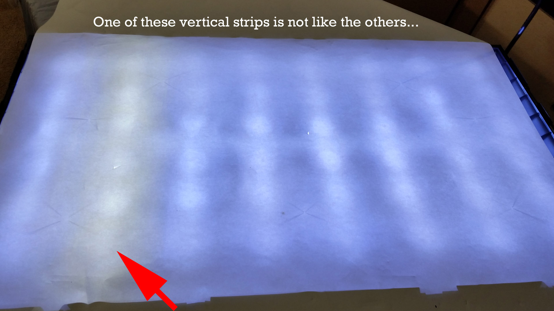
I recently had the pleasure of taking apart a low-cost TV set that had partially failed. The right half of the screen had gone dark, while the left half of the screen looked normal. It was pretty obvious that the backlight had partially failed, but the root cause could not be known until I took the TV apart. The owner had already replaced this TV. There was no pressure to succeed in a repair, since failure would not keep them from watching their favorite programs. It is rare to get the opportunity to solve a problem where the consequences of failure don’t have much impact, but the satisfactions of success can still be felt.
One of the first things I noticed was that this TV set was assembled with screws. It used many screws and none of the nasty hidden latches that some mechanical designers employ. This design approach meant that one could ship the product and know that it would hold together through any reasonable handling. It also meant that disassembly and repair of the guts of the TV are reasonably straightforward. The presence of so many screws probably cost the manufacturer a few extra pennies in factory assembly labor and parts. But to my mind, the gains for ruggedness, rework, and repair far outweighed that tiny cost factor.
Another interesting note was that although the TV set is branded as a Sanyo model DP42D24, the interior components were clearly provided by TCL—a different TV set vendor. This type of re-branding or cross-vendor manufacturing is common in many electronic businesses.
Once the TV set was apart, it became obvious that the backlight consisted of two separate sets of LED strips—four strips for the left half and four strips for the right half of the display. Since one side still illuminated, this meant that the LED driver IC was at least partially functional. After researching the backlight driver IC datasheet, it became clear that the TV manufacturer was using only 2 channels of a 4 channel driver. They likely saved the cost of a few components, some wire, and connectors by only using two of the four channels available. But this decision meant that they were operating the LED stacks at higher voltage. The design appeared to be able to push a lot of current through the LED strips.
I swapped the two (constant-current-sink) outputs and observed that the problem remained on the same side of the display. This meant that both sections of the driver were working, but the problem must be in the LED strips themselves. (If half of the driver circuit were bad, the problem should have followed the connection.)
Next, by powering a single LED strip at a time using a bench supply, it became apparent that one of the six LEDs on only one strip had failed as an open circuit. This stopped current flowing through all LEDs on that 4-strip series (24 LED) string.
The interconnection between the LED strips turned out to be clever as well. Each strip other than the last had an input side connection and a daisy-chain connection to the next strip. By swapping the LED stack and return-current leads, the designer effectively placed two LED strips in the forward current path and two LED strips in the return current path. It took me a little bit of sketching to understand how that worked.
The manufacturer had saved a few pennies by using 3 identical daisy-chain LED strips and one “end” LED strip in each half of the design. This meant that they did not need to use a shorting jumper or connector to close the current path at the end of the LED string. In my experience, using a single type of LED strip PCB with some kind of shorting arrangement for the end strip would have been more common. However, some design teams are less averse to having more unique part numbers in a BOM. This is one of those “taste” issues that probably has no great advantage in either option for this one decision. Maybe I am missing some other additional benefit of using a special “end LED strip.”
My next discovery was that replacing a single LED strip was actually a bad idea. I had ordered one used LED strip on eBay, only to discover that the brightness and “white” color of this replacement strip was significantly different from the other LEDs in my specific TV sample. Stupidly, I repeated this mistake, thinking that the first time had been an aberration. Finally getting smart, I found a complete replacement set of 8 strips on eBay for a reasonable price. If you ever find yourself in a similar circumstance, go ahead and replace the entire backlight array. It is worth the extra cost to have a backlight consistent in hue and brightness.
As an interesting aside, the way that people end up with backlight strips to sell is because occasionally the LCD portion of a screen is physically damaged. Ahem, you know, like a baseball or some other object accidentally thrown through the screen. Their misfortune can be to someone else’s benefit.
Returning to my original point, the designers of the TV set made a series of decisions. Those decisions might have led to the conditions which caused the original failure—probably pushing too much current through the backlight LEDs—but their other decisions made it easier to take the set apart and replace the LED backlight. I found a commenter online who suggested turning your TV set backlight to the lowest brightness you can accept. The reward will be longer backlight life.
Had this design team made the mechanical design too cheap, it would have been far more painful to disassemble, repair, and re-assemble. They also would have suffered more failures in shipping. Taken as a whole, this low-cost TV set probably represented a very reasonable product design. They found a center; they achieved some balance.
* * *
For anyone who might need to deal with a similar repair on this model, I have added some notes below. I hope they might be helpful.
- The backlight LED controller in my set was an MPS MP3398A. A datasheet is available online from MPS.
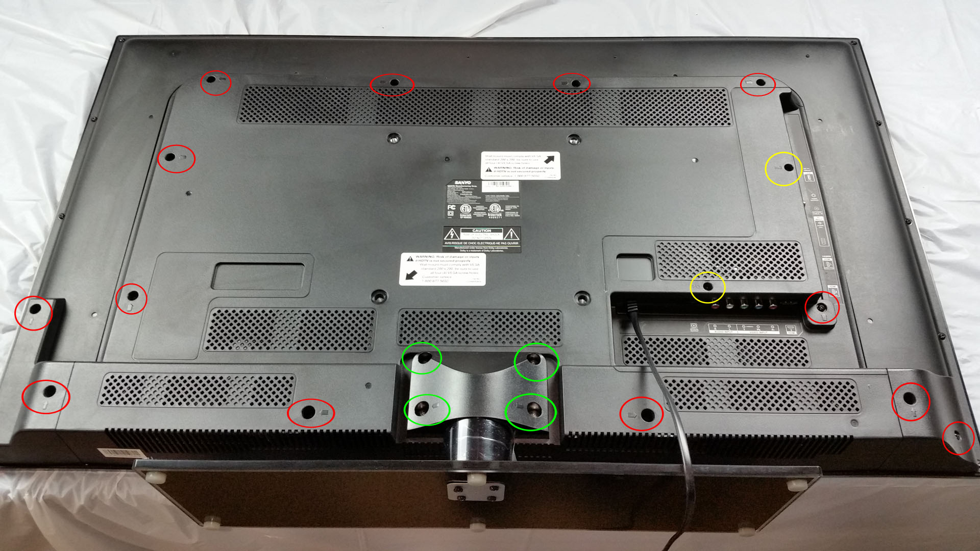
- If the TV set includes a table-stand, remove the 4 large silver-colored phillips-head machine screws and remove the table stand.
- There are 13 (thirteen) black Phillips-head screws on the rear electronics cover. These are all indicated by arrows embossed in the plastic of the rear electronics cover, plus 2 additional plastic edge pieces.
- There are 2 (two) M3 screws through the rear electronics cover which align and hold a metal shield plate around the main PCB.
- There are 4 (four) metal shoulder-washer screws holding the two speakers to the main chassis. Be careful releasing the speaker wire quick-connects. I accidentally broke one speaker connection mount and had to improvise an epoxy-glue repair.
- There are 5 (five) longer black T-9 screws holding the main back cover to the LCD panel bezel.
- There are 16 (sixteen) T-9 head black screws holding the main back cover to the LCD panel bezel.
- Disconnect the IR sensor PCB from its cable. The cable will stay with the main back cover, but the IR sensor PCB stays with the LCD panel bezel.
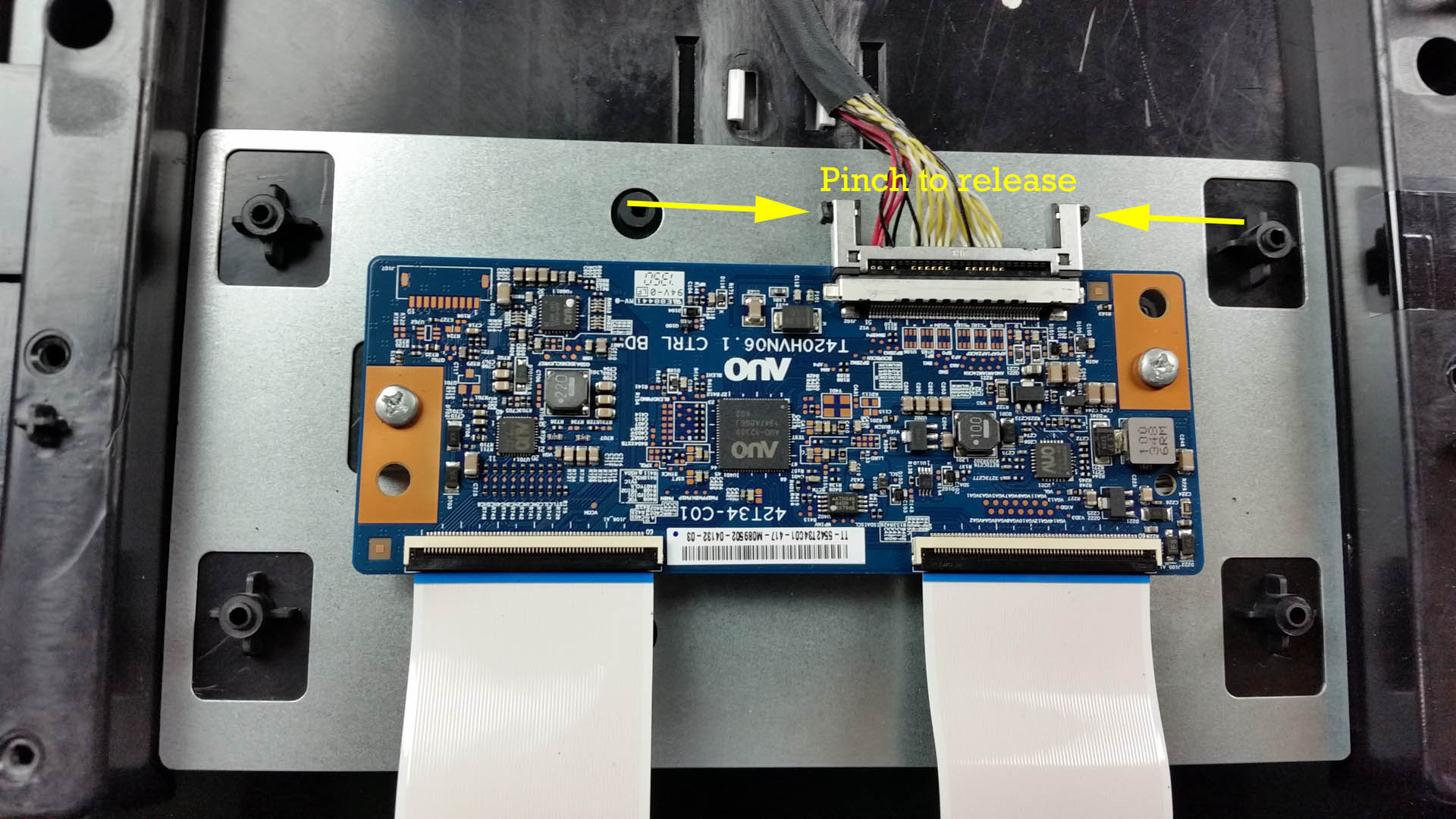
- There are 6 (six) silver screws holding the panel-driver PCB cover plate.
- Disconnect the [main PCB to panel driver] cable at the panel-driver PCB. You will need to pinch both connector release clamps at the ends of the cable connector.
- There are 2 (two) small Phillips-head screws holding the panel-driver PCB to the main back cover. Remove these 2 screws and then carefully deflect the panel-driver PCB out of the way to lift the main back cover off of the LCD panel bezel. Do not aggressively bend or fold the flat-flex connection at the bottom of the panel-driver PCB. These connections go to long, thin vertical PCBs which distribute the panel matrix signals to the actual LCD glass.
- Move the LCD panel bezel assembly to a safe place or lift up and move the main back cover to a safe place where you can work on it separately. (I used a 6 foot long table that could hold both.)
- Turn the main back cover over.
- Remove the light reflector (paper liner) from the main back cover to expose the LED strips. It is held in place with glue or double-sided sticky tape. Take your time separating the paper liner from the main back cover to avoid tearing it. You probably will need to replace or supplement the double-sided sticky tape when re-assembling the TV. I added some washers to the LED strip hold-down screws to provide a positive lock-down for the paper liner.
- Reverse the previous steps to re-assemble the TV set.
If the table-mount is present, remove it first. It is heavy so be sure to support it while loosening the last screws.
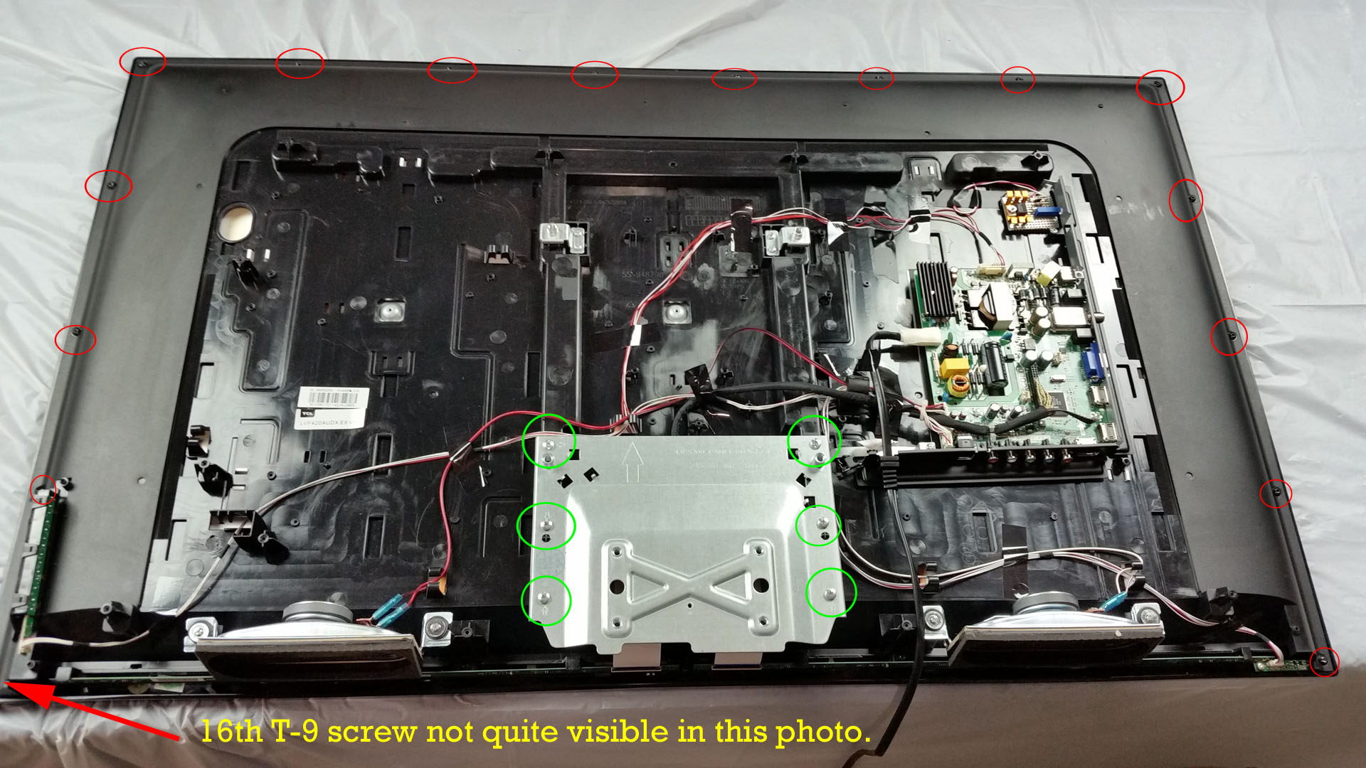
Once the rear electronics cover is removed, you can see all of the internal electronics other than the LCD panel itself.
Take care not to bend, fold, or mutilate the flat-flex connections from the LCD driver board to the panel interface PCBs.
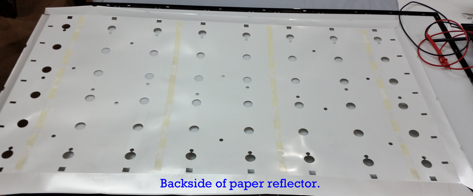
The paper reflector (rear liner) is held in place with double-sided sticky tape. Take your time to separate the liner from the main rear panel.
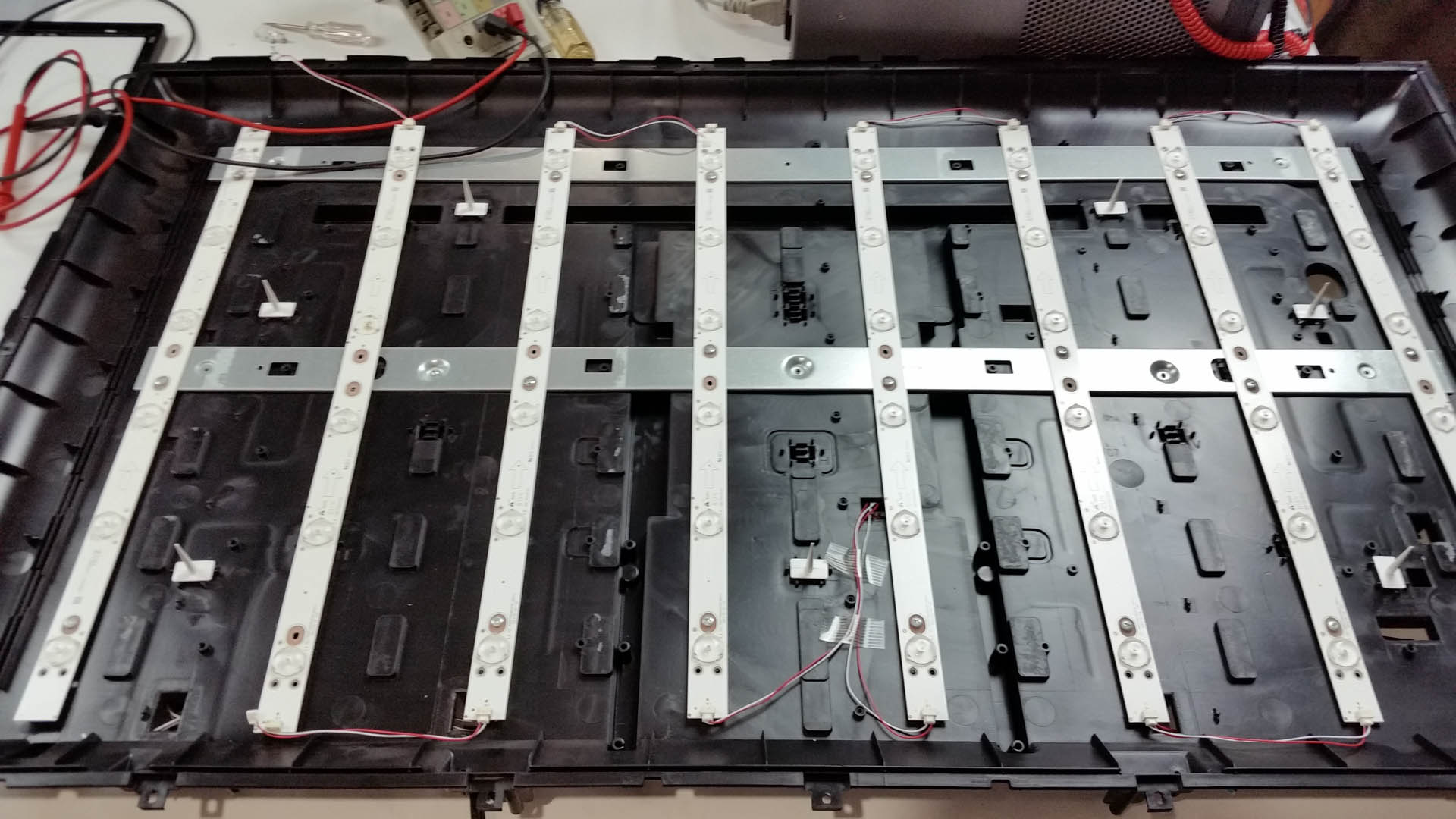
The 8 backlight LED strips are finally visible. Each is held in place with 3 screws. Note that the middle screws are installed in an alternating pattern.
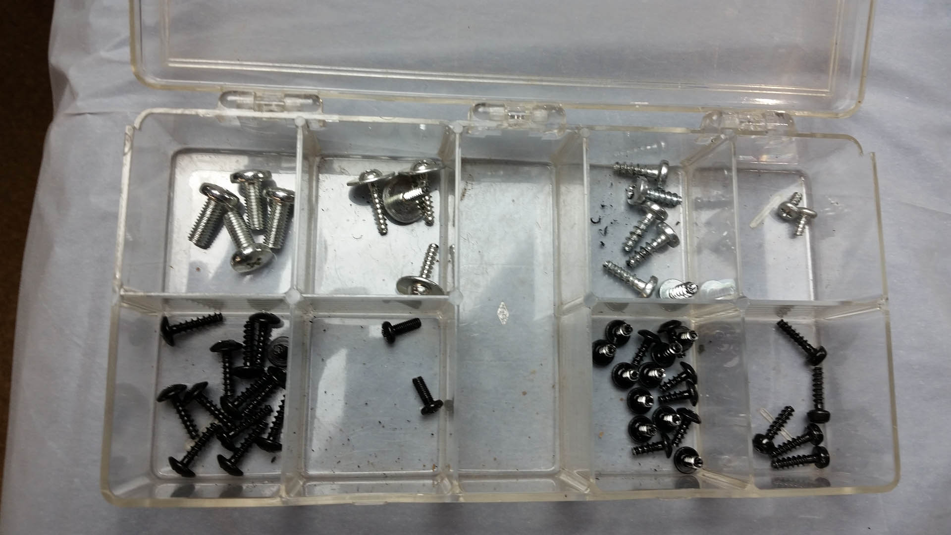
Keep track of your screws or you might get screwed up during re-assembly.